Chapter 3 - Grouping and construction of control valves
Pneumatic valves control pneumatic actuators such as cylinders, rotary actuators etc. The valves control the direction, speed (by flow) and force (by pressure) of the actuator.
We can form the following groups of valves by distinguishing between their functions:
The ISO-symbol tells you a valve's function. By “reading” the symbol correctly you get hints of how to use it.
- Control of the effective direction of actuators – Directional control valves
These valves control the actuators directly or they control other control valves.
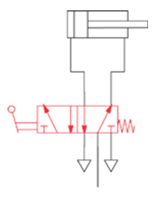
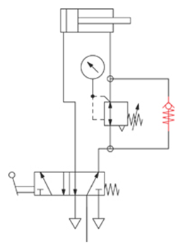
Application example: Control of a double acting cylinder by a 5/2-way hand-lever valve:
- Control of the amount of compressed air into / out of the actuator – Flow regulators
These valves limit the amount of air flowing through them.
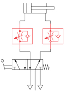
Application example: We can add two uni-directional flow regulators to the example above. They control the speed of the cylinder by limiting the amount of air that is exhausted from it. Limiting the exhaust air is generally the better way in comparison to limiting the air-supply, since it results in a smoother movement of the piston.
- Pressure regulation – Pressure regulators
These products keep the secondary pressure at a distinct level when the incoming pressure is volatile. As you know from Chapter 1, pressure determines the force of an actuator.
Please note: The secondary pressure can only go as high as the entry pressure.
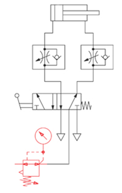
Application example: We can add a pressure regulator to the example above. That way we can control the maximum force of the cylinder by regulating the maximum pressure of the system behind the pressure regulator. A pressure gauge indicates the secondary pressure.
- Quick exhaust – Quick exhaust valves
These valves are designed to exhaust the air from an actuator quickly, which increases the speed of the piston.
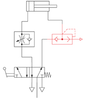
Application example: We can replace one of the flow-regulators with a quick exhaust valve in the example above. By doing so, the air in the chamber of the cylinder exhausts directly into the environment and the air does not flow back through the control valve. This maximizes the push-speed of the piston.
- Logic elements
These valves are not used for directly controlling actuators but to set up pneumatic control systems. Typical elements are: AND, OR, YES, NO. With these functions taken from the Boolean algebra, most (mathematical) problems can be solved.
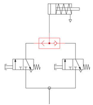
Application example: A single acting cylinder has to be controlled by either one OR the other of two 3/2-way valves. In case you want to make sure that the cylinder only moves if BOTH 3/2-way valves are actuated, replace the OR-gate by an AND-gate.
- Non-return valves = Check valves
Check valves provide a free flow into only one direction. If compressed air comes from the opposite side, it is blocked.
Application example: In order to save compressed air on a double acting cylinder that is „doing work“ in only one direction, the air-pressure that is needed to return the piston can be reduced significantly. A second pressure regulator is required for that. This regulator has to have a by-pass when the air exhausts from the relevant cylinder-side. The “one-way” by-pass is realized by using a check-valve.
A typical application of a check-valve is the combination with a flow-regulator (see above example). This product is called Uni-directional flow regulator. In one direction the air can by-pass the regulator, whereas in the other direction the free flow is blocked and the air is forced to go through the regulator.
General information on directional control valves
Directional control valves are the most important elements of a pneumatic control system.
In any fluid application they are utilized to define the route of the medium. They are used to control cylinders or other actuators. They can also control the movement and the direction of pneumatic motors or control other control valves.
Directional control valves are not designed for regulating pressure or flow.
We can form categories of directional control valves as follows:
- By basic design
- Spool valves
- Poppet valves
- By actuation
- Mechanically actuated
- Manually actuated
- Pneumatically actuated
- Electrically actuated (solenoid valves)
- By the number of (stable) positions
- One stable position: single solenoid / single pilot valve or spring return valve.
- Two stable positions: double solenoid / pilot valve, lever valve indexed.
- 3-positions valves.
- Flow in basic position
- For 2/2-way and 3/2-way valves with spring return
- Normally open
- Normally closed
- For 3/3, 4/3- and 5/3-way valves
- Centre closed
- Centre exhausted
- Centre pressurized
- By the number of ports/positions
- 2/2-way (2 ports, 2 positions)
- 3/2-way (3 ports, 3 positions)
- 3/3-way (3 ports, 3 positions)
- 4/2-way (4 ports, 2 positions - only one exhaustport)
- 5/2-way (5 ports, 2 positions)
- 4/3-way (4 ports, 3 positions - only one exhaustport)
- 5/3-way (5 ports, 3 positions)
The most common types are in bold. Besides the ones mentioned above there are more possibilities for special applications (e.g. 5/4-way valves, 7/3-way valves, ...)
Basic design of directional control valves
Let's have a look at the basic difference between spool and poppet valves.
One of the basic elements of any directional control valve is the valve body. The body holds the parts of the valve together. The second important element is the moving part(s), which blocks and opens ports, or connects two or more of them with each other.
The closing element can either be a spool or a valve disk. Therefore we distinguish between:
- Spool valves and
- Poppet valves.
Spool valves
In spool-valves the different ports are connected by axially moving a cylindrical spool.
The drawings below display the closed and open position of a spool valve.
Poppet valves
In a poppet valve a valve-disc is pushed onto the valve-seat. When the disc is released again, the valve opens.
The drawings below display the closed and open position of a poppet valve.
Grouping directional control valves by modes of actuation
Actuation means the source of energy which moves the closing element (disc or spool):
| mechanically | a part of a machine pushes onto a stem or a roller-lever of the valve |
| manually | a human being operates a knob or a lever |
| pneumatically | a pressure signal moves the spool or the disc |
| electrically/ solenoid |
the plunger of a solenoid opens a poppet valve (lifts the disc on the seat) |
| solenoid pilot | the plunger of a solenoid opens a poppet valve, the moves a spool or a second (larger) disc. |
Solenoid valves can be distinguished as:
- Direct acting valves
The (poppet) valve is directly opened by electric energy.
- Piloted valves (solenoid pilot spool valves)
The main valve is generally a spool valve. The spool is driven by compressed air. This pilot air is controlled by a poppet valve. Part of the energy used to control the valve is supplied by the medium.
The method of using the energy of the medium is not only used in spool valves. Poppet valves or diaphragm valves can be designed like that, too.
- Solenoid valves with external pilot feed
This function is very similar to the solenoid pilot valves. The difference is that it's not the energy of the medium of the main valve which is used to move the spool, but instead there is an additional port for compressed air. The solenoid system is separately supplied through that.
Valves are available with different numbers of (stable) positions:
- One stable position
As soon as the actuation is gone (i.e. the pneumatic signal or electric energy is cut, the button is released) the spool or the disc is forced back into its basic position. This movement can be powered either by a mechanical spring or by the energy of the medium (“air spring”).
- Two stable positions
Whenever the actuation stops, the spool or disc stays in its current position until there is an actuation into the opposite direction.
- 3 positions valves
The spool / disc can generate 3 different kinds of connections of the ports (very rarely more).
Manually actuated valves can be designed with 3 stable positions or in a way that the spool is driven into centre position by mechanical springs. Valves that are actuated in other ways are normally only available with a basic position.
Description number of ports and number of positions:
The following will only offer a first glance at this topic. You will receive more information in a later chapter.
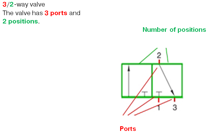
The valve is called X/Y-way valve, where X represents the number of ports in the main valve and Y the number of positons.
Example:
In Europe you will find mostly 2/2-, 3/2-, 5/2- and 5/3-way valves. In the USA 4/2 and 4/3-way valves are common.
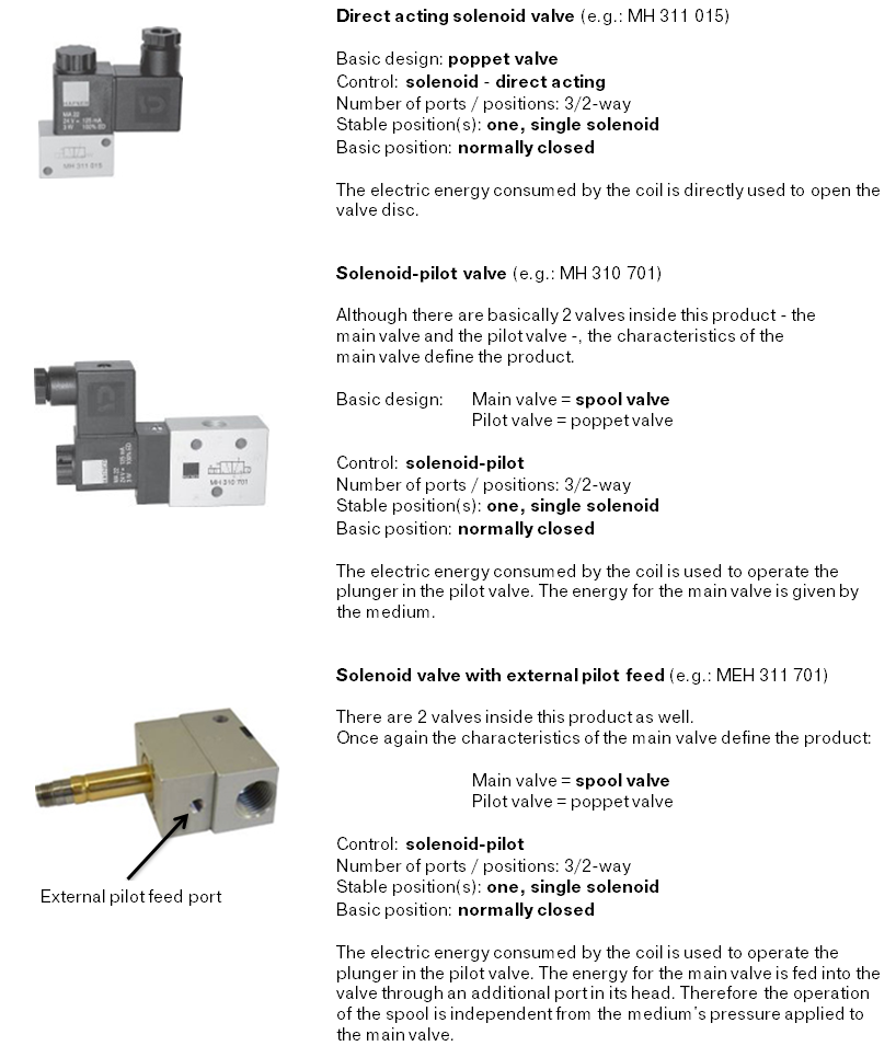
Application examples, distinguishing between solenoid valves:
In the next chapter we will have a more detailed look at the function of directional control valves.

